Using Cans for EMI Shielding on Your PCB--Factory make EMI shielding
Preventing electromagnetic interference is critical for proper functioning of your PCB design. In addition to good design practices, can shields can also be used to isolate sensitive components.
What is a can?
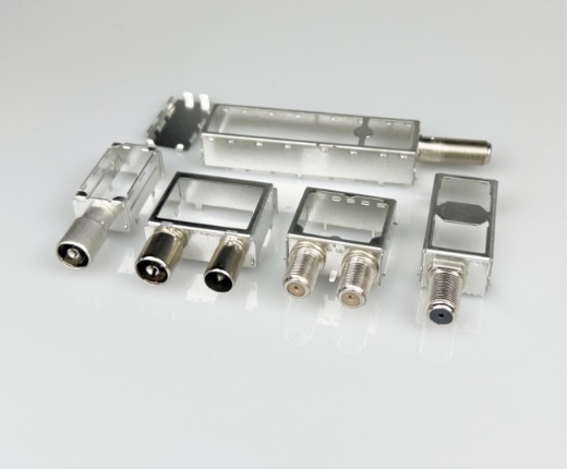
EMI can shields may also be called cans, cages, covers, or lids, depending on where you look for parts. They are basically metal boxes that attach to your PCB to enclose part of the circuitry on the surface.
RF can shields are metal enclosures that help provide board level shielding after your initial design procedures to optimize any EMI and emissions.
The metal used depends on your application and the price you’re willing to pay. I recommend talking directly to a manufacturer to be sure you’ll get the right material for your product. The usual options are:
Steel: Tin or zinc plated steel, stainless steel
Aluminum: Usually tin-plated aluminum
Brass
Copper alloys: Copper beryllium is especially common
Nickel
Silver
Tin plated plastic
The metal enclosure of the can keeps EMI from entering or leaving the covered region. Many can shields have a grid of holes in the metal that helps with thermal management, while still providing the shielding effect of a conductive cover over your components.
An ideal shield would completely encapsulate your components. Unfortunately, that leaves no options for inputs and outputs, or power and grounding, so a can will still have some leakage. If necessary, you can supplement the can with additional shielding, like gaskets, mesh, and films.
When should I use a can?
When you’re designing a PCB, you should first design your board to minimize emissions with good design practices like short traces, proper grounding, and component placement to minimize emissions. Using shields should never take precedence over good board design for EMI management, but they are a great next step.
Shields are particularly appropriate when you need to isolate components from EMI that might occur elsewhere on the PCB. They are most often used over the RF output, or inputs and amplifier stages, since these are the sections of a circuit most likely to be affected by/cause EMI. In our design, the shield covered both the RF module and amplifier to isolate them from other noise in the circuit.
EMC sensitive components can also be shielded to prevent interference. Finally, you might want to shield high-speed components like oscillators to prevent them from creating interference across the board.
How do I incorporate it into my design?
When you’ve identified the components or subassemblies that can most benefit from can shielding, you can calculate the shield size you need. This can be tricky because most manufacturers give you external dimensions, even though you need to know internal clearance to fit around your components. I speak from experience when I say that height is especially critical and easily overlooked.
To attach the can to the board, you add solder pads around the necessary components on your PCB and ground them appropriately. There are also clips or frames that hold the can onto the PCB. If you are in an early version of the design, I recommend a removable option. It makes rework under the can much easier. verlooked.
To attach the can to the board, you add solder pads around the necessary components on your PCB and ground them appropriately. There are also clips or frames that hold the can onto the PCB. If you are in an early version of the design, I recommend a removable option. It makes rework under the can much easier. The shield or clips can be attached during automated fabrication processes by soldering the shield to surface mount pads.
You can have custom shields made, if necessary. It’s more expensive, but if you have a non-standard area that you need to be shielded, and don’t want to waste board space, it’s worth it. Also, be aware if you have traces on the surface of the board that the can would contact. You should have recesses cut into the edge of the can to prevent shorting on the board. I know someone who got around that by always using clips, but I worried that large mashing fingers might push the edge of the can into contact with the trace anyway.
While you can’t protect your PCBs from every accident that comes along, you can certainly shield your boards from themselves (and hopefully some probing fingers). I really like having modular RF designs that you can reuse in future products, and minimize your non-recurring design effort.